Riyas P.K-Fab Academy 2016
Electronics Production
The assignment for this week is to make a FabISP.This involves cutting the circuit board, soldering the components on the board, and then programming the microcontroller.I used 'hello.ISP.44' design from here..You can find various designs from there.
Cutting the Circuit Board
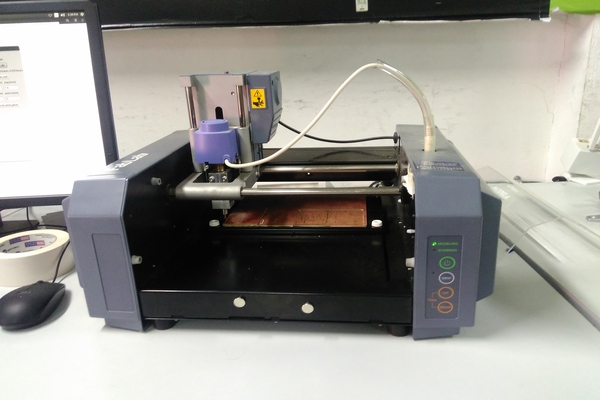
We are using a Roland Modela MDX-20 for circuit cutting,I watched a perfect tutorial of using it.Like vinyl cutter we use fab modules to control it.This can be done in few steps.
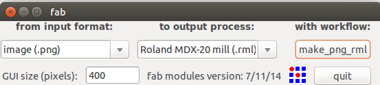
- Type 'fab' in terminal(Ubuntu),it will bring up following window
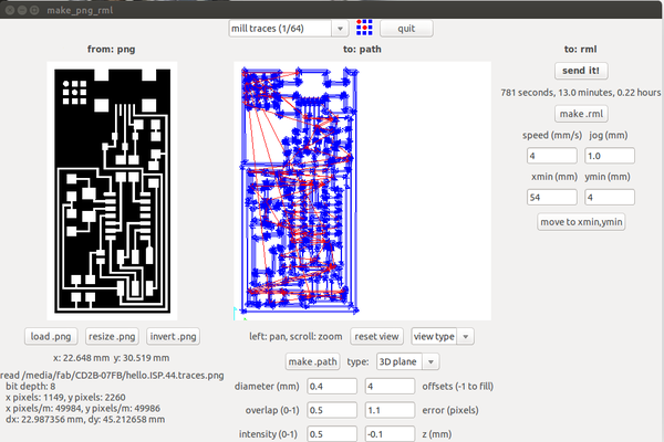
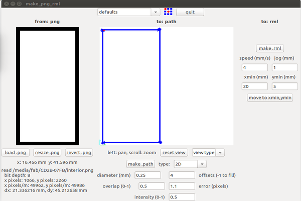
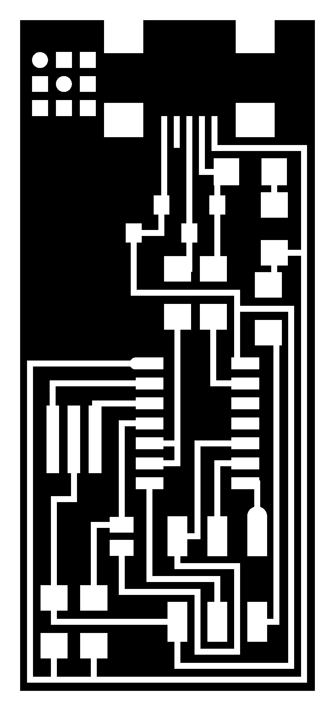
- Click on make_png_rml.When the make_png_rml window opens, load your png file for the circuit and select the mill traces (1/64) option. I also changed the xmin (mm) to 54 and the ymin (mm) to 4 so that it would cut the board out at about the middle of my circuit board. Click on the make.path button to see a preview.You also need to set the number of offsets based upon how much material you want to remove and how long you have to cut the board.I selected it as 4.
- Cover the entire back of the circuit board with double-sided tape. Be careful to not overlap the tape or get wrinkles in it. The circuit board needs to mount completely flat.
- With the Modela mill on, pressing the view button toggles view mode on and off. When in view mode the green LED near the view button is lit and the machine moves the spindle up and the work table all the way forward and to the left.
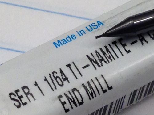
- Carefully remove the existing tool from the spindle and install the 1/64" flat endmill. There should be two hex set screws holding the tool in the spindle.For now, make the tool fairly short and tighten the set screws just enough so the tool doesn't fall out.
- Tape your circuit board down firmly. Notice that we have an acrylic sacrificial spoil board under the circuit board. We machine this to make sure we have a very flat surface. Otherwise we had problems with the circuit board not cutting at the same depth over the entire surface of the circuit board.
- Press the View button to exit the view mode. The spindle should move back above the part.
- When you turn off the Modela mill it forgets where it z=zero location is. You'll need to move the endmill over your board so you can lower it to the copper. I used the move to xmin,ymin button in the make_png_rml module. This moves the modela to the x and y I will use as the origin when I generate the rml file. In my case it is xmin=20 and ymin-5.
- Now set the z=zero location. Press the down button to lower the spindle until the tool is just a short distance from touching the top of the circuit board. Do not plunge into the circuit board with the tool.
- While holding the tool with two fingers, loosen both the set screws on the spindle, and carefully lower the tool tip until it touches the top surface of the circuit board. Do not let the tool just drop down, it may break the tool tip. Also remember that the tool is very sharp. While holding the tool firmly touching the top of the circuit board, tighten both spindle set screws snuggly.
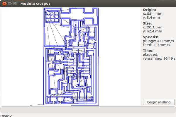
- Click on make.rml in the make_png_rml module and then click on send it!. When the Modela output screen appears click on Begin Milling.
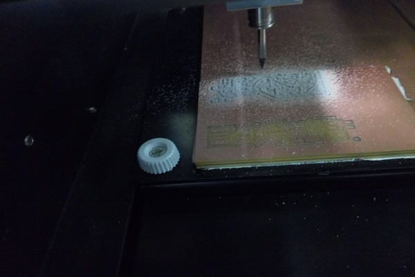
- Wait for the Modela to do its thing
- When the machine is done cutting out around the circuit traces, repeat the process to cut out the board using a 1/32" end mill.
- Use the png file for the outline of the circuit board. Select cutout board (1/32).
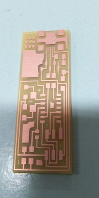
- When the machine is done, vacuum up the debris and remove the board. Removing the board and leftover tape was not easy.
- Clean up the board.
Soldering the Circuit Components
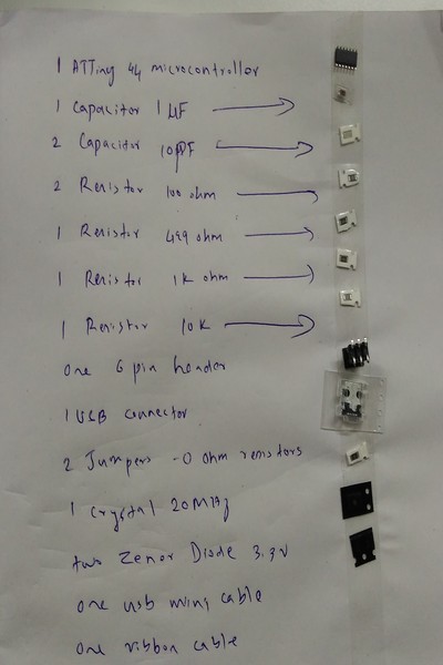
- First I listed out the required components in a paper and using two side tape,I placed the components along with it.
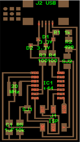
- Then I started soldering the components according to the circuit diagram.
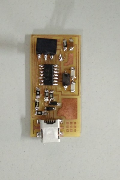
- After some struggle i finally finished the soldering.
Programming the fabisp
Before you can use your FabISP the ATTiny44 Microprocessor chip on it has to be programmed.
- To program the ATTiny44, I needed to install AVRDude (for programming AVR microcontrollers)and GCC(to compile C code).Since I am using Ubuntu, I typed the following using the terminal interface:
- I then downloaded the firmware zip from electronics production page. I unzipped the file into a folder on the desktop.
- In the firmware zip file.I had to edit the edit the make file to configure it for the in-system programmer ,I used another fabISP. So I had to edit the make file:
- Navigate to the directory where you saved the FabISP firmware. If you followed the instructions above, this will be the desktop. Open your terminal / command line interface and move to the firmware directory.
- It was success.
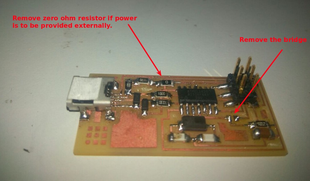
- After you have programmed the board, remove the 0 ohm resistor if power is to be provided externally and solder bridge.
               sudo apt-get install flex byacc bison gcc libusb-dev
                    - type "y" when asked

               sudo apt-get install gcc-avr
                    - type "y" when asked

               sudo apt-get install avr-libc
                    - type "y" when asked
AVRDUDE = avrdude -c usbtiny -p $(DEVICE)
               cd Desktop/firmware

               make clean

               make hex

               make fuse

               make program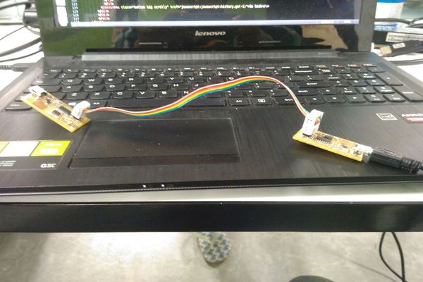
Problems faced:
During programing there was a problem,it won't fuse and showed some errors.After checking the connections using a multimeter I found out that there was a problem in soldering.So I reflowed the components of the ISP board.Then I tried to program it again and this time it was successfull.
Here is a video of programming a board using FabISP: